
The RJ45 Connection/Wiring Diagrams and Standards for Networking
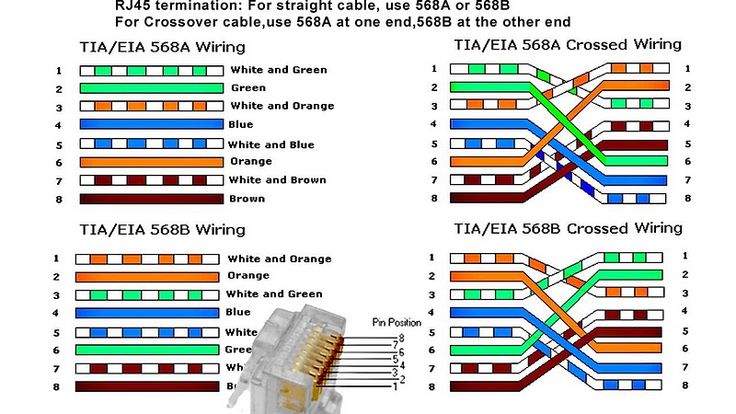
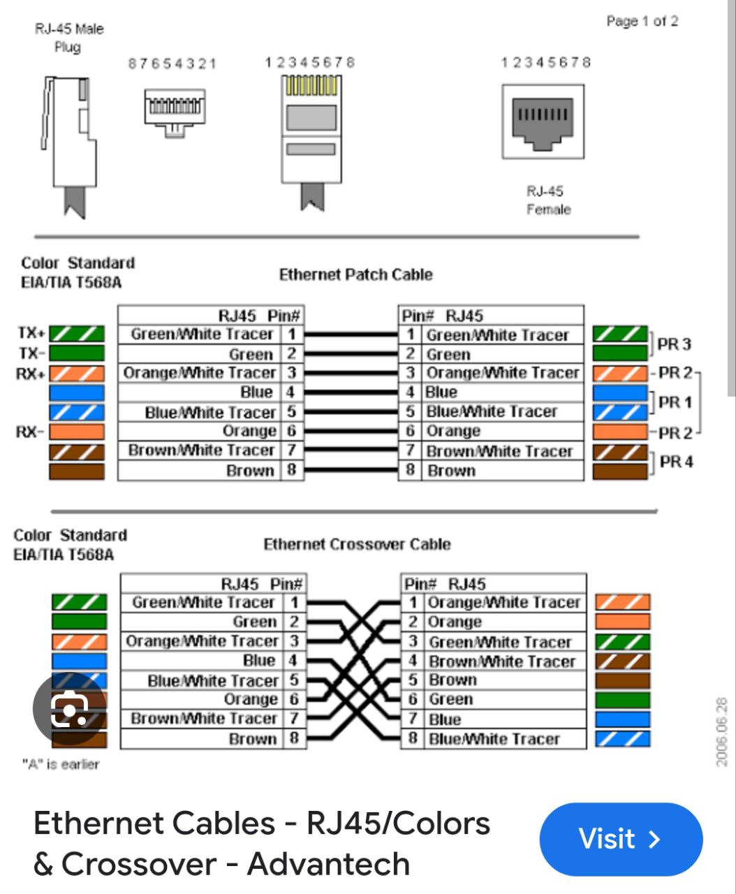
An RJ45 connector is a standardized, modular connector with 8 pins, commonly used for Ethernet connections. There are two primary wiring standards for RJ45 connectors: T568A and T568B. Both standards use the same 8-position, 8-contact (8P8C) design, but with a different color code arrangement for the wires.
RJ45 Wiring Diagrams and Standards:
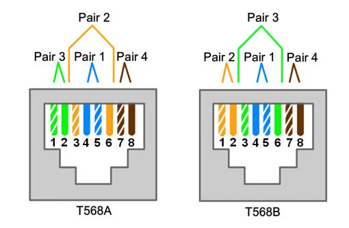
T568A:
Starts with white/green, then green, followed by white/orange, blue, white/blue, orange, white/brown, and brown.
T568B:
Starts with white/orange, then orange, followed by white/green, blue, white/blue, green, white/brown, and brown.
Types of RJ45 Cables:
Straight-through:
Both ends of the cable use the same wiring standard (either T568A or T568B).

Crossover:
The transmit and receive pins on one end are crossed over with the corresponding pins on the other end. This allows direct connection between similar devices, like computer to computer.
When to use which standard:
T568B:
Most commonly used in modern networking and is the default wiring scheme for structured cabling.
Straight-through:
Used for connecting devices with different functions, such as a computer to a switch or router.
Crossover:
Used for connecting similar devices directly, like computer to computer.
Auto-MDIX:
Many modern devices automatically detect the cable type and adjust accordingly, simplifying the use of straight-through cables in most situations.
Key points about RJ45 connectors:
They are used with various Ethernet cable categories, including Cat5e, Cat6, and higher.
The maximum length for an Ethernet cable using RJ45 connectors is 100 meters.
RJ45 connectors are not compatible with RJ11 connectors (used for telephones).